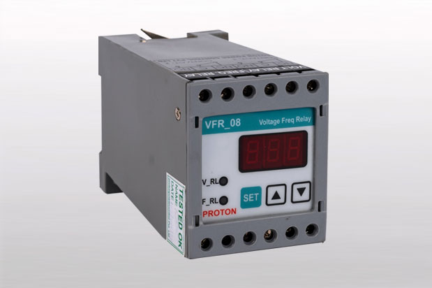
Protection of 3 Phase devices against Over voltage, Under voltage,(UB) Single Phasing,(SPP) Over Frequency, Under Frequency, Reverse Phasing & Unbalance supply are one of the major issues in electrical systems. For safe running of 3-phase devices, special protections that keep a continuous watch on supply conditions are very essential. The major cause of maximum load burn-out is overloading,which occurs due to Unbalance Supply, Single Phasing or Reverse phasing conditions. VFR3P detects such conditions & protects the load from the burn out. 'Proton's VFR 3P' offers above protections along with 3 digit display showing R-Y,Y-B,B-R, voltages in scanning mode with precise accuracy.
Low/High voltage tripping to ensures trouble free running of 3-phase Loads, and also protection is provided against Over /Under Frequency
- Supply voltage : 3 Phase 415 VAC, 50 Hz (R, Y, B & N) (No auxiliary supply)
- Output Contacts : Two SPDT (C-N/O-N/C) Relay, Rating 5A at 250V AC
- Indications : FAULT (UB/SPP/REVP, UV, OV, UF, OF): RED LED,
- RELAY ON : GREEN LED
- Relative Humidity : 10 to 95% RH
- Mounting : Din Rail
- Dimensions : 55(W) X 75(H) X 110(D) mm.
- Keys :
- SET : SET key, Press to enter into SET Mode
- INC : Upward Arrow key, Press to increment the set point.
- DEC : Downward Arrow key, To Decrement the setpoint.
- Microcontroller based technology.
- Protection against under voltage, Over voltage, Over Frequency, Under Frequency, Single Phasing & Reverse Phasing
- All the set points settable by keys.
- Trip Delay for Under voltage & Unbalance is settable
- Reverse Phasing Protection can be bypass through settings.
- Indications for Voltage & Frequency Relay ON.
- Message Display for (UB/SPP/REVP, UV, OV, UF, OF)Faults.
- No separate auxiliary supply required.
-
1) If the input supply is within the range of the fault limit limits then On Timer starts decrementing on display & after set on Time over Relay will de ON with RLY indication glowing
2)If OV , UV, OF, UF, SPP/ reverse phasing / Unbalance occurs in the supply then relay will be OFF after the trip delay of that particular fault & LED starts blinking
3) If any phase to Voltage increases above OV set point belay will trip after trip delay (100)ms ) over .If that particular phase to phase voltage reduces below COV set point Relay will be on after the set rest delay is over
4) If any Phase to Phase Voltage increases / reduces above / the UB set point compared to other two Phase to Phase voltages , Relay will trip after delay over If that particular phase to phase voltage reduces / increases below / above (UB set point -/+ 10-V ) relay will be ON after the set reset delay over If the frequency reduces below UF or increases above OF then the relay will trip . Hysteresis is 1H2
5)If any of the Phase fails , Relay will trip after trip delay (100ms) over If all phases are present , relay will be ON after the set reset delay is over
6) If Phase sequence is changed to R-B-Y/Y-R-B/B-R-Y; Relay will trip after the trip delay (100 ms) over . if phase sequence is corrected to R-Y-B, relay will after the delay over UB /SPP/REVP,UV,UF, OF.


